Tuesday, November 18, 2014

Moteino 3.3V arduino

I recently came across a low power 3.3v Arduino UNO board from LowPowerLab. Moteino consists of an atmega328p,  serial flash, RFM69 or RFM12B wireless module.

http://lowpowerlab.com/moteino/

Here is an link to the Moteino framework video by Felix Rusu from LowPowerLab submitted for the Hackaday Prize entry.


I have a few of the Moteino and MoteinoMega modules with on board flash and RFM69HW.


Sunday, March 3, 2013

SD Card library and example on olimexino stm32

Today I tried to configure SD card library and run examples on olimexino stm32. This will use the microSD card slot on board. You can read more about micro SD card on Wikipedia here.

Maple IDE can be used to program the board. Download Maple IDE.

I downloaded SDCARD library and examples - Maple SDCARD_Lib + Examples MapleIDE leaflabs forums.


Olimexino stm32 board front side picture

Olimexino stm32 board back side pictrure with microSD card slot visible

I download the files from the above link. Unzipped the files to a folder and copied the two unzipped folders to the /libraries/ folder in my Maple IDE installation folder. There is a readme.txt file in the unzipped  folder. 
Sdcard I used is in fat16 format.How to Format a Fat16 SD Card

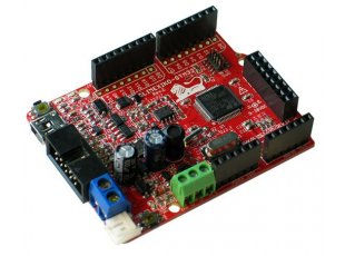
I used a Sandisk micro sdcard of 2GB and inserted it into the card slot at the back of the board.
Lets start with an example. I fired the Maple IDE. Then selected the my first example by selecting File -> Examples -.SdFat -> MapleExamples -> SDFatInfo.

Maple STM32 SDFatFileInfo example selection File -> Examples -.SdFat -> MapleExamples -> SDFatInfo.


As easy as it gets I pressed Ctrl+R key to compile the code. When the example code is compiled it also compiles the library files.
Then pressed Ctrl+U to upload the code to the maple Olimexino stm32 board.

Once the code is uploaded then to see the card information on the serial port in Maple itself select Tools -> Serial port or Ctrl+Shift+M keys to open Serial Monitor window.
In the text bar next to 'Send' button entered a character (I pressed 'a') and clicked 'Send'.

SDFatFileInfo Serial Monitor output

I could see lots of card info. How simple. And I have not done any coding for sdcard yet:).
So as a next step I wanted to see the above info on Microsoft HyperTerminal instead of the Maple build in Serial Monitor.

So I closed the Serial monitor window, and opened HyperTerminal. Opened a new connection, gave a name for the connection, selected the com port where the stm32 board is connected,  selected the baud  rate as per the settings shown in the figure here.
Olimexino STM32 hyperteminal settings


Then when connected pressed any key("a") in my case on the keyboard.
Olimexino STM32 SDFatFileInfo hyperterminal output

Here is the output.

Now that I get card info, I tried a few examples for file read and write already in the SDCard library and examples for Maple that we download earlier. I found a simple example to write file and read a file on a microSD Card.

I fired my Maple IDE. Then started the example by selecting File -> Examples -.SdFat -> SDClass -> ReadWrite.

Compiled the code (Ctrl+R), then uploaded firmware to stm32 board (Ctrl+U).
Fired my HyperTerminal at 115200 baud rate. Pressed a key on the keyboard and got the following output


It shows that initialization of SDCard was done successfully, write to file test.txt was successful. The read back of file contents and display on the serial port is also complete.

That was so easy to read and write to a SDCard. Now I can write my own programs to use SD library and examples. There are lots of other examples available in the library and should be easy to to implement modify in any application.

This blog is not meant to be a manual so if you find any mistakes please point out to me. If any one has any comments/feedback please post. Also if you find the information useful please link to my blog.

Over the next few blogs I will be writing on using temperature sensors and XBEE's. I am also looking at Jeenode and Seeeduino Stalker v2.3

Tuesday, February 19, 2013

Olimexino-STM32 Hello World example

After the first blink example on OLIMEXINO-STM32 board using the MAPLE ide, the next and obvious example is "Hello World". I have modified the Blink without delay example available in Maple and added Serial code.
The serial output will be available on the SerialUSB port through the mini usb cable connected to the PC. In addition to three serial ports, the Maple’s STM32 microprocessor includes a dedicated USB peripheral. This peripheral is used to emulate a regular serial port for use as a terminal. The emulated terminal is relatively slow; it is best for transferring data at regular serial speeds (kilobaud).
Library access to the emulated serial port is provided through the SerialUSB object. You can mostly use SerialUSB as a drop-in replacement for Serial1, Serial2, and Serial3.

The baud rate by default is 115200.

Here is the code. Copy it to a blank sketch and compile.


/*
  Hello World -Blink without delay
  Send out "Hello World" over SerialUsb port at 115200 baud rate.
  Turns on and off the built-in light emitting diode (LED), without
  using the delay() function.  This means that other code can run at
  the same time without being interrupted by the LED code.

  created 2005
  by David A. Mellis
  modified 17 Jun 2009
  by Tom Igoe
  modified for Maple 27 May 2011
  by Marti Bolivar
  Modified by Jaime Fernandes 17 Feb 2013
  Uses the inbuilt millis() function to get time elapsed in milliseconds
*/

// Variables:
int previousMillis = 0;        // will store the last time the LED was updated
int interval = 1000;            // interval at which to blink (in milliseconds)

void setup() {
    // Set up the built-in LED pin as output:
    pinMode(BOARD_LED_PIN, OUTPUT);

   
    //Send Hello World string over serial port
    SerialUSB.println("Hello World");
}

void loop() {
// Check to see if it's time to blink the LED; that is, if the
// difference between the current time and last time we blinked
// the LED is bigger than the interval at which we want to blink
// the LED.
// Every time the led is toggled serial port sends out 
// a "Toggled LED" message

// millis function information
    if (millis() - previousMillis > interval) {
        // Save the last time you blinked the LED
        previousMillis = millis();
        // If the LED is off, turn it on, and vice-versa:
        toggleLED();
        SerialUSB.println("Toggled LED");
    }
}


If compile is successful, download to the stm32 board. Refer to my previous post to see how to compile the code and download to the board. To see the output, on the menu bar select Tools -> Serial Monitor. Once the code runs you should see BOARD_LED_PIN (green LED) being toggled every (interval)milliseconds. The serial port should also display "Toggled LED" message.


Saturday, February 16, 2013

OLIMEXINO-STM32 BOARD

I recently purchased an OLIMEXINO-STM32 board which is based on Arduino which is an open-source electronics prototyping platform, designed to make the process of using electronics in multidisciplinary projects easily accessible. 

The arduino hardware consists of a simple open hardware design with an Atmel AVR processor and on-board I/O support. The software consists of a standard programming language and the boot loader that runs on the Arduino hardware.

Arduino hardware is programmed using a Wiring-based language (syntax + libraries), similar to C++ with some simplifications and modifications, and a Processing-based Integrated Development Environment (IDE). 

The Arduino project began in Ivrea, Italy in 2005 aiming to make a device for controlling student-built interaction design projects less expensively than other prototyping systems available at the time. 

Founders Massimo Banzi and David Cuartielles named the project after a local bar named Arduino. The name is an Italian masculine first name, meaning "strong friend". The English pronunciation is "Hardwin", a namesake of Arduino of Ivrea.

 More information could be found at the creators web page http://arduino.cc/ and in the Arduino Wiki http://en.wikipedia.org/wiki/Arduino. Arduino inspired many derivatives. Maple project is one such developed by a team from MIT which is based on ARM7 STM32F103RBT6. 

The board uses a IDE similar to Arduino and found at http://www.leaflabs.com. Maple uses 3.3V for everything instead of the Arduino's 5V (though some of the I/O pins are 5V tolerant). Olimexino STM32 is based on MAPLE board with some improvements. 


Here at the list of features of the OLIMEXINO-STM32 Board mentioned at https://www.olimex.com/Products/Duino/STM32/OLIMEXINO-STM32/
  • Industrial temperature range -25 to +85C 
  • Power input voltage from 9 to 32V DC 
  • Ultra low power voltage regulators and power consumption is only a few microamps 
  • Li-Ion rechargable battery power supply option with on-board charger 
  • UEXT connector allows many modules like RF, ZIGBEE, GSM, GPS to be connected 
  • RTC functionality supported with 32.768 kHz crystal oscillator 
  • Micro -SD Card socket 
  • "Noise Immune" design 
  • LEDs and the BUTTONs are on the edge of the board so there is easy access even if the boards have shields on them 
  • 4 Mount holes CAN driver on board The LEDs and the BUTTONs are on the edge of the board so there is easy access even if the boards have shields on them mini USB connector is used which is common and used in most cell phones, so you do not have to buy other cables 
The board can be purchased on Olimex site here and mouser.com here.

Various UEXT modules are available at https://www.olimex.com/Products/Modules/ and on MOUSER site 

Here is the manual of the board. Download Board Manual 

Maple IDE can be used to program the board. Download Maple IDE.

Here is a document which explains how to install the Maple IDE.

OLIMEXINO-STM32 REV.D Board Schematic in PDF format Download


Once the Maple IDE is downloaded, unzip to a folder. 
Connect the board to the PC using USB cable. Refer to instructions here for installing board usb drivers Run the MAPLE environment by opening maple-ide.exe in the folder you extracted earlier (the downloaded IDE).

The following settings are needed for your OLIMEXINO-STM32 to work properly: In the Tools/Serial port menu choose the serial COM port you found earlier. 

Next, go into the Tools/Board menu and choose the option shown in the picture. 


Now lets start with example codes. In the Menu Select File -> Examples -> Digital ->Blink This will open up a window with the blink example code. 


Similar to code structure  on Arduino IDE this example has two functions setup() and loop(). The code inside setup() function will run once on start up. So you can write code here to initialize hardware , variables etc. The code inside loop() function will be called repeatedly. 

In our example inside setup() function pin BOARD_LED_PIN is initialized as output. In loop() function toggleLED() will turn LED from off to on and on to off delay(1000) function gives a delay of 1000 milliseconds.

Now lets compile this code. In the above Blink example code window Menu bar select Sketch -> Verify/Compile or Control + R keys.


The code will be compiled and report success/ or fail message. 

Next is to upload the code to the board. Press the reset button on the board and click on the upload button shown below in the IDE. When searching for DFU shows on the IDE, release the reset button and the code should be uploaded to the board.


When the code runs the BOARD_LED_PIN LED which is green in color will be ON for 1sec and OFF for 1sec.

Wednesday, February 13, 2013

My first blog

This is my first blog entry. I will attempt to blog my experiments with Arduino and its clones in future blogs. Lets see how far I can go.