I recently purchased an OLIMEXINO-STM32 board which is based on Arduino which is an open-source electronics prototyping platform, designed to make the process of using electronics in multidisciplinary projects easily accessible.
The arduino hardware consists of a simple open hardware design with an Atmel AVR processor and on-board I/O support. The software consists of a standard programming language and the boot loader that runs on the Arduino hardware.
Arduino hardware is programmed using a Wiring-based language (syntax + libraries), similar to C++ with some simplifications and modifications, and a Processing-based Integrated Development Environment (IDE).
The Arduino project began in Ivrea, Italy in 2005 aiming to make a device for controlling student-built interaction design projects less expensively than other prototyping systems available at the time.
Founders Massimo Banzi and David Cuartielles named the project after a local bar named Arduino. The name is an Italian masculine first name, meaning "strong friend". The English pronunciation is "Hardwin", a namesake of Arduino of Ivrea.
More information could be found at the creators web page http://arduino.cc/ and in the Arduino Wiki http://en.wikipedia.org/wiki/Arduino.
Arduino inspired many derivatives. Maple project is one such developed by a team from MIT which is based on ARM7 STM32F103RBT6.
The board uses a IDE similar to Arduino and found at http://www.leaflabs.com.
Maple uses 3.3V for everything instead of the Arduino's 5V (though some of the I/O pins are 5V tolerant). Olimexino STM32 is based on MAPLE board with some improvements.
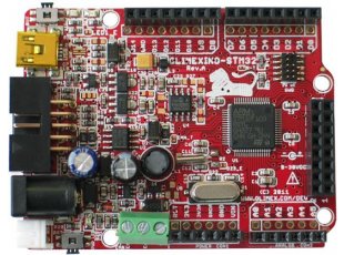
Here at the list of features of the OLIMEXINO-STM32 Board mentioned at https://www.olimex.com/Products/Duino/STM32/OLIMEXINO-STM32/
- Industrial temperature range -25 to +85C
- Power input voltage from 9 to 32V DC
- Ultra low power voltage regulators and power consumption is only a few microamps
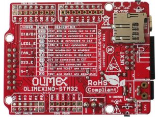
- Li-Ion rechargable battery power supply option with on-board charger
- UEXT connector allows many modules like RF, ZIGBEE, GSM, GPS to be connected
- RTC functionality supported with 32.768 kHz crystal oscillator
- Micro -SD Card socket
- "Noise Immune" design
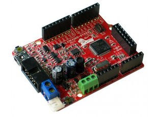
- LEDs and the BUTTONs are on the edge of the board so there is easy access even if the boards have shields on them
- 4 Mount holes CAN driver on board The LEDs and the BUTTONs are on the edge of the board so there is easy access even if the boards have shields on them mini USB connector is used which is common and used in most cell phones, so you do not have to buy other cables
Various UEXT modules are available at https://www.olimex.com/Products/Modules/ and on MOUSER site
Here is the manual of the board. Download Board Manual
Maple IDE can be used to program the board. Download Maple IDE.
Here is a document which explains how to install the Maple IDE.
OLIMEXINO-STM32 REV.D Board Schematic in PDF format Download.
Once the Maple IDE is downloaded, unzip to a folder.
Connect the board to the PC using USB cable. Refer to instructions here for installing board usb drivers
Run the MAPLE environment by opening maple-ide.exe in the folder you extracted
earlier (the downloaded IDE).

The following settings are needed for your
OLIMEXINO-STM32 to work properly:
In the Tools/Serial port menu choose the serial COM port you found earlier.
Next, go into the Tools/Board menu and choose the option shown in the picture.

Now lets start with example codes.
In the Menu Select File -> Examples -> Digital ->Blink
This will open up a window with the blink example code.

Similar to code structure on Arduino IDE this example has two functions setup() and loop().
The code inside setup() function will run once on start up. So you can write code here to initialize hardware , variables etc.
The code inside loop() function will be called repeatedly.
In our example inside setup() function pin BOARD_LED_PIN is initialized as output.
In loop() function toggleLED() will turn LED from off to on and on to off
delay(1000) function gives a delay of 1000 milliseconds.
Now lets compile this code.
In the above Blink example code window Menu bar select Sketch -> Verify/Compile or Control + R keys.

The code will be compiled and report success/ or fail message.
Next is to upload the code to the board. Press the reset button on the board and click on the upload button shown below in the IDE. When searching for DFU shows on the IDE, release the reset button and the code should be uploaded to the board.

When the code runs the BOARD_LED_PIN LED which is green in color will be ON for 1sec and OFF for 1sec.
No comments:
Post a Comment